1. Which best describes the benefit of using Frame Relay as opposed to a leased line or ISDN service?
• Customers can define their virtual circuit needs in far greater combinations, with increments as small as 64 kbps.
• Customers pay for an end-to-end connection that includes the local loop and the network link.
• Customers only pay for the local loop and the bandwidth they purchase from the network provider.
• Connecting new sites requires new lower cost circuit installations when compared to ISDN dialup costs or adding additional
• hardware for leased service.
2. What two methods does Frame Relay technology use to process frames that contain errors? (Choose two.)
• Frame Relay services depend on the upper layer protocols to handle error recovery.
• It requires the receiving device to request that the sender retransmit erroneous frames.
• FECN, BECN, and DE bits are set in the frames to minimize errors.
• The receiving device drops any frames that contain errors without notifying the sender.
• The frame relay switch notifies the sender that errors were detected.
3. What best describes the use of a data-link connection identifier (DLCI)?
• local address identifying a destination router across a Frame Relay network
• locally significant address used to identify a virtual circuit
• logical address identifying the interface between a router and a Frame Relay switch
• logical address used to identify the DCE
4. What is created between two DTEs in a Frame Relay network?
• ISDN circuit
• limited access circuit
• switched parallel circuit
• virtual circuit
5. Which two items allow the router to map data link layer addresses to network layer addresses in a Frame Relay network?
• (Choose two.)
• ARP
• RARP
• Proxy ARP
• Inverse ARP
• LMI status messages
• ICMP
6.
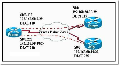
Refer to the exhibit. A ping is sent to address 192.168.50.10 from the Peanut router. Which DLCI will be used to send the ping?
• 110
• 115
• 220
• 225
7.

Refer to the exhibit. Which two outcomes occur from the configuration shown? (Choose two.)
• The broadcasts will be forwarded to 10.1.1.1.
• The router will use DLCI 22 to forward data to 10.1.1.1.
• DLCI 22 will replace the MAC address in the ARP table for entry 10.1.1.1
• Frames arriving on interface serial 0/0/0 of RT_1 will have a data link layer address of 22.
• Inverse-ARP will now add an entry for 10.1.1.1 into the Frame Relay map table using DLCI 22.
8. Refer to the exhibit. What effect does the point-to-point configuration on subinterface S0/0.110 have on the operation of the
• router?
• It helps to conserve IP addresses.
• It establishes multiple PVC connections to multiple physical interfaces.
• It eliminates split horizon issues without increasing the likelihood of routing loops.
• It requires the configuration of the encapsulation command on the subinterface.
9. Which three actions does a Frame Relay switch perform when it detects an excessive build-up of frames in its queue? (Choose three.)
• puts a hold on accepting frames in excess of the CIR
• drops frames from the queue that have the DE bit set
• reduces the number of frames it sends over the link
• re-negotiates flow control with the connected device
• sets the FECN bit on all frames it receives on the congested link
• sets the BECN bit on all frames it places on the congested link
10.

Refer to the exhibit. Which two statements are true given the output shown? (Choose two.)
• The IP address of the local Frame Relay interface is 172.16.1.4.
• The local DLCI number is 401.
• Inverse ARP is being used on this connection.
• This interface is in the active state and in the process of negotiating configuration parameters.
• Multicast is not enabled on this connection.
11.
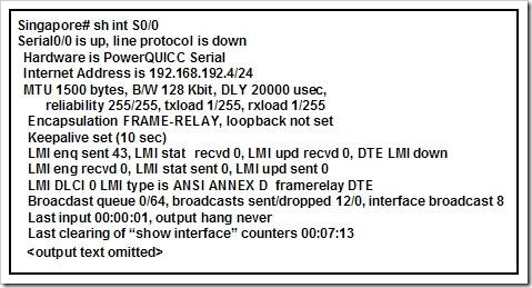
Refer to the exhibit. When troubleshooting a Frame Relay connection, an administrator entered the show interfaces s0/0 command and received the output shown in the exhibit. What are two probable reasons for this problem? (Choose two.)
• The cable between the CSU/DSU and the router is disconnected.
• The serial 0/0 interface is shutdown.
• The router is not configured for the same Frame Relay PVC as the switch.
• The LMI type on the Frame Relay switch is NOT ANSI.
• The address of the Frame Relay switch is not in the routing table.
12.
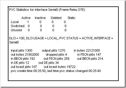
Refer to the exhibit. What can be determined about the Frame Relay switch from the output shown?
• It is currently not transmitting data.
• It is in the process of establishing the PVC.
• It has put a hold on processing frames in excess of the CIR.
• It is experiencing congestion.
13.
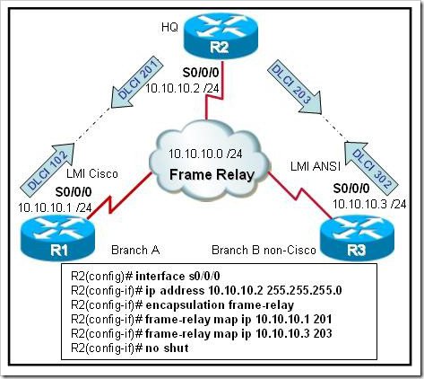
Refer to the exhibit. Router R2 is part of a Frame Relay network that uses OSPF for IP routing. After the commands that are shown are entered, R2 will not exchange OSPF information correctly. What is the likely cause?
• The frame-relay map command requires the broadcast keyword.
• The DLCIs on each end of the PVCs are not identical.
• The R2 S0/0/0 interface has not been brought online.
• The LMI or Inverse ARP or both are not working.
14. Which statement about Frame Relay subinterfaces is correct?
• Multipoint interfaces will automatically forward routing broadcasts but will consume more IP addresses than point-to-point
• subinterfaces will consume.
• Point-to-point subinterfaces act like leased lines and eliminate split-horizon routing issues.
• Interfaces with multiple PVCs require a separate subinterface for each PVC.
• Multipoint configurations cannot use subinterfaces.
15.
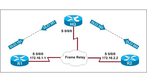
Refer to the exhibit. You are a network administrator who has been tasked with completing the Frame Relay topology that
• interconnects two remote sites. Router HQ belongs to both the 172.16.1.0/24 and 172.16.2.0/24 subnets with IP addresses of
• 172.16.1.3 and 172.16.2.3 respectively. Traffic between R1 and R2 must travel through HQ first. How should the serial interface
• on HQ be configured to complete the topology?
• one multipoint subinterface
• two point-to-point subinterfaces
• with the physical interface configured with two ip addresses
• one IP address on a point-to-point subinterface and one IP address on the physical interface
16. What consideration must be taken into account if RIP is used on Frame Relay multiaccess networks?
• To forward routing updates, address-to-DLCI mapping must be done via the use of the frame-relay map command
• coupled with the broadcast keyword.
• Inverse ARP must be enabled to turn routing update broadcasts into unicast traffic that can be propagated to other Frame Relay
• nodes.
• Because broadcast traffic is not supported, RIPv1 cannot be implemented on Frame Relay networks.
• To forward broadcast routing updates, dynamic mapping must be enabled.
17.
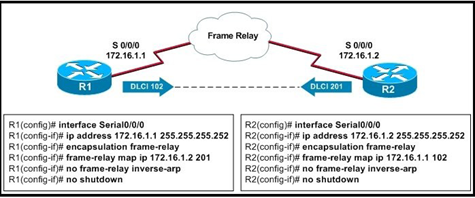
Refer to the exhibit. Which statement explains why the Frame Relay connection between R1 and R2 is failing?
• Split horizon must be disabled.
• The LMI type must be specified.
• Logical subinterfaces must be used instead.
• The frame-relay map commands are using incorrect DLCIs.
18.
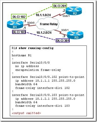
Refer to the exhibit. Router R1 has been configured for Frame Relay connectivity to routers R2 and R3. Which set of configuration options for routers R2 and R3 would provide each router connectivity to R1?
• R2(config)# interface serial0/0/1
R2(config-if)# frame-relay map ip 10.1.1.1 102
R3(config)# interface serial0/0/1
R3(config-if)# frame-relay map ip 10.1.2.1 103
• R2(config)# interface serial0/0/1
R2(config-if)# frame-relay map ip 10.1.1.1 102
R2(config-if)# frame-relay map ip 10.1.2.3 301
• R3(config)# interface serial0/0/1
R3(config-if)# frame-relay map ip 10.1.2.1 103
R3(config-if)# frame-relay map ip 10.1.1.2 201
• R2(config)# interface serial0/0/1.201 point-to-point
R2(config-if)# no frame-relay invers-arp
R3(config)# interface serial0/0/1.301 point-to-point
R3(config-if)# no frame-relay invers-arp
• R2(config)# interface serial0/0/1.201 point-to-point
R2(config-if)# frame-relay interface-dlci 201
R3(config)# interface serial0/0/1.301 point-to-point
R3(config-if)# frame-relay interface-dlci 301
19.
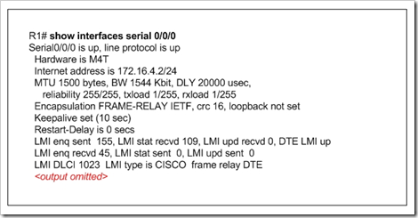
Refer to the exhibit. What can be known about the configuration of router R1 from the output?
• The Frame Relay LMI DLCI has been incorrectly configured as DLCI 1023.
• The Frame Relay LMI type has been changed from its default.
• The Serial 0/0/0 interface has been configured as a data communications equipment device.
• The command encapsulation frame-relay ietf has been used on the Serial 0/0/0 interface.
20.
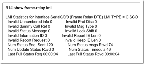
Refer to the exhibit. What can be determined about the configuration of router R1 from the exhibited output?
• LMI updates are not being received properly.
• The LMI type for the Serial 0/0/0 interface has been left to its default configuration.
• Cisco HDLC is used as a Layer 2 encapsulation protocol on the Serial 0/0/0 interface.
• The Serial 0/0/0 interface has been configured as a data communications equipment device.
21.

Refer to the exhibit. What can be determined from the output?
• Serial 0/0/0 has been configured with an DLCI of 201.
• Serial 0/0/0 has the feature frame-relay inverse-arp enabled.
• Serial 0/0/0 has been configured with an IP address of 172.16.4.3.
• Serial 0/0/0 has been configured with the command frame-relay map ip 172.16.4.3 201 broadcast.
22.
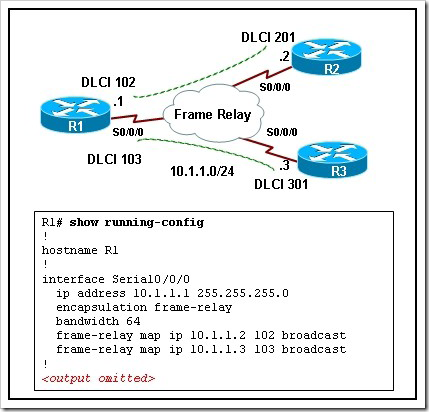
Refer to the exhibit. Router R1 has been configured for Frame Relay connectivity to routers R2 and R3. What configuration option should be configured on the R2 and R3 serial interfaces in order for all routers to ping each other successfully?
• R2(config-if)# frame-relay interface-dlci 201 broadcast
R3(config-if)# frame-relay interface-dlci 301 broadcast
• R2(config-if)# frame-relay map ip 10.1.1.1 201 broadcast
R3(config-if)# frame-relay map ip 10.1.1.1 301 broadcast
• R2(config-if)# frame-relay map ip 10.1.1.3 201 broadcast
R3(config-if)# frame-relay map ip 10.1.1.2 301 broadcast
• R2(config-if)# frame-relay map ip 10.1.1.1 201 broadcast
R2(config-if)# frame-relay map ip 10.1.1.3 201 broadcast
R3(config-if)# frame-relay map ip 10.1.1.1 301 broadcast
R3(config-if)# frame-relay map ip 10.1.1.2 301 broadcast
But if you find the same answers for all the Module anywhere in the internet.
And if you have an Answers are correct 100% or if you find an answer, What is wrong in this blog. please send me. (Post in blog or Send Email )
Because,I will update the blog…
Monday, December 15, 2008
CCNA Exploration 4 - Module 3 Exam Answers Version 4.0
ป้ายกำกับ:
Accessing the WAN
,
CCNA Exploration 4 Version 4.0
Subscribe to:
Post Comments
(
Atom
)
No comments :
Post a Comment